In this section we propose an energy-efficient approach with dynamic max–min planning for intelligent networking of 5G networks.
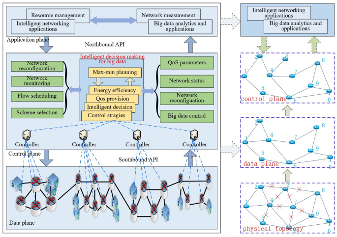
Max–min planning for energy efficiency with network-wide perspective for multiple controllers, with red notation ’x’ denoting low load or idle links. Network is divided into data plane and control plane, with the former responsible for data forwarding and with the latter responsible for network connectivity.
System model
The related 5G architecture used in this model is based on Heterogeneous Cloud Radio Access Network (H-CRAN) that combines the advantages of Heterogeneous Network (HetNet) and Cloud Radio Access Network (C-RAN). HetNet separates the control and data plane using High Power Node (HPN). C-RAN utilizes Remote Radio Head (RRH) to efficiently support local businesses. Different from C-RAN, the Base Band processing Unit (BBU) pool in H-CRAN connects to the existing HPN, which allows for the full utilization of macro base stations in cellular networks such as 3G and 4G to achieve seamless coverage and separation of control and service plane functions. HPN is used for controlling information distribution across the entire network, separating the centralized control cloud function module from the BBU pool. In H-CRAN, all control signals and system broadcast information are sent by HPN to User Equipment (UE), which enables RRH to adaptively sleep according to user business needs, effectively saving energy consumption and achieving user centered green and energy-saving communication20. Based on the architecture of H-CRAN, we introduce the intelligent networking structure shown in Fig. 2. The separation of the control plane and data plane in H-CRAN allows us to use the control plane to generate the max–min planning and distribute the energy-efficient planning scheme to the data plane, which determines the on/off state of links. The structure in Fig. 2 is illustrated with multiple geographically distributed networks. Each sub-network is controlled by a distributed SDN controller that is aware of the state of the data plane and responsible for distributing the forwarding rules. All distributed controllers receive the global intelligent decision-making module that generates the max–min planning scheme. The states of the distributed controllers synchronize through distributed consensus algorithms. Let n denote the node index, with \(n\in {1, 2,\ldots , 10}\). The end-to-end traffic demands are divided into \(\pi \in {1, 2,\ldots , z}\) time slots according to traffic nature in a day, where the size of each time slot is not equal due to different properties in each hour per day, and denotes the number of divided time slots. In each time slot, the physical topology in Fig. 2 is exploited to build data plane and control plane, respectively, subjective to minimum energy consumption. The data plane in each time slot achieves maximum network flow delivery matching the end-to-end traffic demands, that is, the data plane delivers data packets via maximum link utilization while the paths built by maximum network flow method can exactly meet the end-to-end traffic demands. The control plane in each time slot guarantees network connectivity and is used for controlling network, such as link activation and sleeping in each time slot. Hence, for the network shown in Fig. 2, there exist \(\pi\) data planes and control planes in a day, respectively. In each time slot, all data planes and control planes consume the minimum amount of energy from a network-wide perspective. In such a case, the minimum energy consumption is obtained to forward the maximum end-to-end traffic demands in each time slot.
Max–min design formulation
The time in a day is divided into different time slots. In each time slot, there is a corresponding data plane and control plane. In each time slot, the end-to-end traffic demand, physical topology, maximum network flow, and minimum energy consumption are all considered to build the decision process. The process aims at establishing the optimal data plane and control plane with minimum energy consumption for matching end-to-end traffic demands.
Maximum Network Flows: Given a network \(G = (V, E)\), the capacity of edge \(
$$\begin{aligned} \sum \limits _{{v_j} \in V} {{f_{{v_i}{v_j}}}} – \sum \limits _{{v_j} \in V} {{f_{{v_j}{v_i}}}} = {v_f} \quad {v_i} \in S,\ \left\langle {{v_i}{v_j}} \right\rangle \in E \end{aligned}$$
(1)
Similarly, flow traffic conservation constraints for destination nodes are formulated as follows:
$$\begin{aligned} \sum \limits _{{v_j} \in V} {{f_{{v_i}{v_j}}}} – \sum \limits _{{v_j} \in V} {{f_{{v_j}{v_i}}}} = – {v_f} \quad {v_i} \in D,\ \left\langle {{v_i}{v_j}} \right\rangle \in E \end{aligned}$$
(2)
The flow traffic conservation constraints of intermediate nodes are formulated as:
$$\begin{aligned} \sum \limits _{{v_j} \in V} {{f_{{v_i}{v_j}}}} – \sum \limits _{{v_j} \in V} {{f_{{v_j}{v_i}}}} = 0 \quad {v_i} \notin S,\ {v_i} \notin D,\ \left\langle {{v_i}{v_j}} \right\rangle \in \end{aligned}$$
(3)
The capacity constraints of links are formulated as follows:
$$\begin{aligned} 0 \le {f_{{v_i}{v_j}}} \le {C_{{v_i}{v_j}}},\ \left\langle {{v_i}{v_j}} \right\rangle \in E \end{aligned}$$
(4)
For the network with N source and N destination nodes, respectively, there exist \(K = N \times N\) origin-destination (OD) pairs. The multi-source and multi-destination maximum flow model can be described as:
$$\begin{aligned} Max{\hspace{1.0pt}} {\hspace{1.0pt}} {\hspace{1.0pt}} {\hspace{1.0pt}} {\hspace{1.0pt}} \sum \limits _{k = 1}^K {\sum \limits _{p \in {P_k}} {w_{kp} } } \end{aligned}$$
(5)
where \(S_k\) and \(D_k\) are the source node and destination node of OD pair k, respectively; \(P_k\) is its path set; \(w_{ke}\) denotes the traffic of path set \(P_k\) traversing link e. \(w_{kp}\) should follow:
$$\begin{aligned}&w_{kp} \ge 0, \quad \forall k = 1,2,\ldots ,K,\ \forall p \in {P_k} \end{aligned}$$
(6)
$$\begin{aligned}&w_{ke} \le {C_e}, \quad \forall k = 1,2, \cdots K,\ \forall e \in E \end{aligned}$$
(7)
$$\begin{aligned}&\sum \limits _{k = 1}^K {w_{ke} } \le {C_e}, \quad \forall e \in E \end{aligned}$$
(8)
$$\begin{aligned}&\sum \limits _{p \in {P_k}} {w_{kp}} = {\Gamma ^k},\quad \forall k = 1,2, \cdots K \end{aligned}$$
(9)
Minimum Network Energy Consumption: To realize minimum network energy consumption, we define a rate-adaptive energy consumption function as:
$$\begin{aligned} F({x_{ij}}) = {\left\{ \begin{array}{ll} 0, & {x_{ij}} = 0 \\ \beta \cdot \left[ {\delta \cdot {C_{ij}} + (1 – \delta ) \cdot \frac{{{x_{ij}}^2}}{{{C_{ij}}}}} \right] , & 0 < {\hspace{1.0pt}} {x_{ij}} \le {C_{ij}} \end{array}\right. } \end{aligned}$$
(10)
where \(x_{ij}\) and \(C_{ij}\) are the load and capacity of link \(l_{ij}\); \(\delta\) and \(\beta\) are function curve coefficients. When link \(l_{ij}\) is closed, its load and energy consumption are zero; or otherwise their relationship is described by Equation 10. The minimum network energy consumption is to minimize the total energy consumption \(\sum \limits _{(i,j) \in E} {F({x_{ij}})}\) of networks.
Max–min Model: To achieve maximum energy efficiency, the maximum throughput and minimum energy consumption of networks are aimed at. Our max–min model is written as:
$$\begin{aligned} Max \quad \sum \limits _{k = 1}^K {\sum \limits _{p \in {P_k}} {w_{kp} } } – \lambda \sum \limits _{(i,j) \in E}{F({x_{ij}})} \end{aligned}$$
(11)
where link utilization is \(w_{kp} \ge 0{\hspace{1.0pt}} {\hspace{1.0pt}}\), \(\forall k = 1,2,\ldots ,K{\hspace{1.0pt}} {\hspace{1.0pt}}\), \(\forall p \in {P_k}\); link capacity constraints are defined as:
$$\begin{aligned}&\sum \limits _{k = 1}^K {\sum \limits _{p \in P_k^H} {{U_{kpe}}w_{kp} } \le \alpha \times {C_e}}, \quad \forall e \in E \end{aligned}$$
(12)
$$\begin{aligned}&\sum \limits _{p \in {P_k}} {w_{kp} \le } {\Gamma ^k}, \quad \forall k = 1,2,\ldots ,K \end{aligned}$$
(13)
$$\begin{aligned}&\sum \limits _{p \in P_k^H} {{U_{kpe}}w_{kp} } \le \alpha \times {C_e}, \quad \forall k = 1,2, \cdots K, \forall e \in E \end{aligned}$$
(14)
The upper constraint of path traffic is:
$$\begin{aligned} \sum \limits _{p \in {P_k}} {w_{kp} \ge \beta } {\Gamma ^k}, \quad \forall k = 1,2,\ldots ,K \end{aligned}$$
(15)
The maximum hop number constraint is:
$$\begin{aligned} hop(p) \le H,\quad \forall p \in {P_k}, \forall k = 1,2,\ldots ,K \end{aligned}$$
(16)
where \(\lambda\)is a Lagrange parameter. The optimization model is an integer linear programming model, which can be solved exactly by CPLEX21.
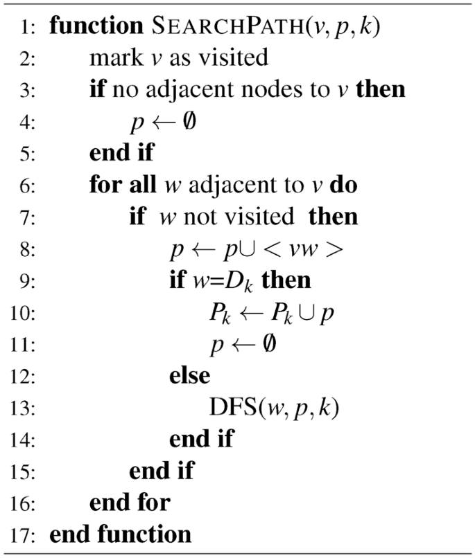
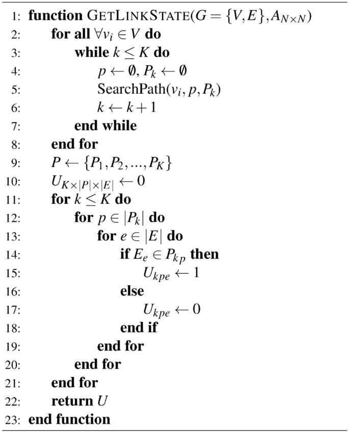
Optimal Solution: First, we propose a the link state matrix calculation algorithm, shown as Algorithm 1 and 2. For each OD pair with its source node \(S_k\) and the destination node \(D_k\), initiate \({P_k} = \emptyset\). Initialize the path set of data plane as \(P = \emptyset\). Then calculate P according to the depth-first search algorithm finding out all paths set between any two nodes in the directed connected graph. For \(\forall {v_i} \in V\) and \(\forall \left\langle {{v_i}{v_j}} \right\rangle \in E\), perform depth-first search, where “1” represents the node has been visited; “0” represents the node is not visited. Calculate associated edge set \(RE_i\) of node \(v_i\) according to adjacency matrix. If edge \(\left\langle {{v_i}{v_j}} \right\rangle \in R{E_i}\) and the mark of \(\left\langle {{v_i}{v_j}} \right\rangle\) and \({v_j}\) is “0”, then mark both \({v_j}\) and \(\left\langle {{v_i}{v_j}} \right\rangle\) as “1”. If \({v_j} \ne {D_k}\), set \({v_i} = {v_j}\) and continue the process above to conduct deep search from node \({v_j}\) until \({v_j} = {D_k}\) and save p as successful path to \(P_k\). Otherwise, abandon this path and keep the mark values of the vertex and links. Back to node \(v_i\), if \({v_i} \ne {S_k}\), continue the process above to obtain the path set of the entire data plane \(P = \left\{ {{P_1},{P_2}, \cdots ,{P_k}} \right\}\). Then calculate link state matrix. Initiate link set E of the data plane and path set \(P_k^H\) of combinations k for \(\forall p \in {P_k}^H\) and \(\forall e \in E\) . If the path p occupies link e , let \({U_{kpe}} = 1\) , or otherwise \({U_{kpe}} = 0\). Given adjacency matrix \({A_{N \times N}}\), traffic request matrix \({\Gamma _{N \times N}}\), link capacity \({C_e}\), maximum link utilization ratio \(\alpha\), lower bound factor of end-to-end traffic rate \(\beta\) and the obtained U, build the model in 10 and solve it using CPLEX to attain energy-efficient data plane and control plane.


